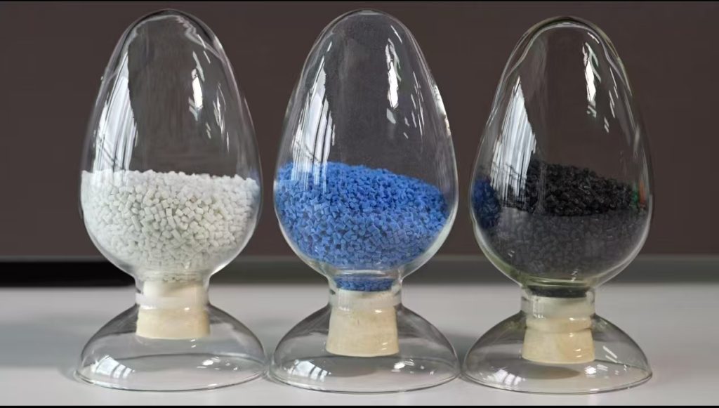
This guide compares PA66 GF30 and PA66 GF50 by stiffness, strength, heat, moisture condition, molding risk and application requirements.
Use the Exact PA66 GF30 or GF50 Datasheet
The verified material library lists PA66 GF30 Datasheet.pdf en PA66 GF50 Datasheet.pdf as separate standard files. It also lists separate GF30 FR and GF50 FR files. Confirm the full grade name before applying any value to a drawing or approval record.
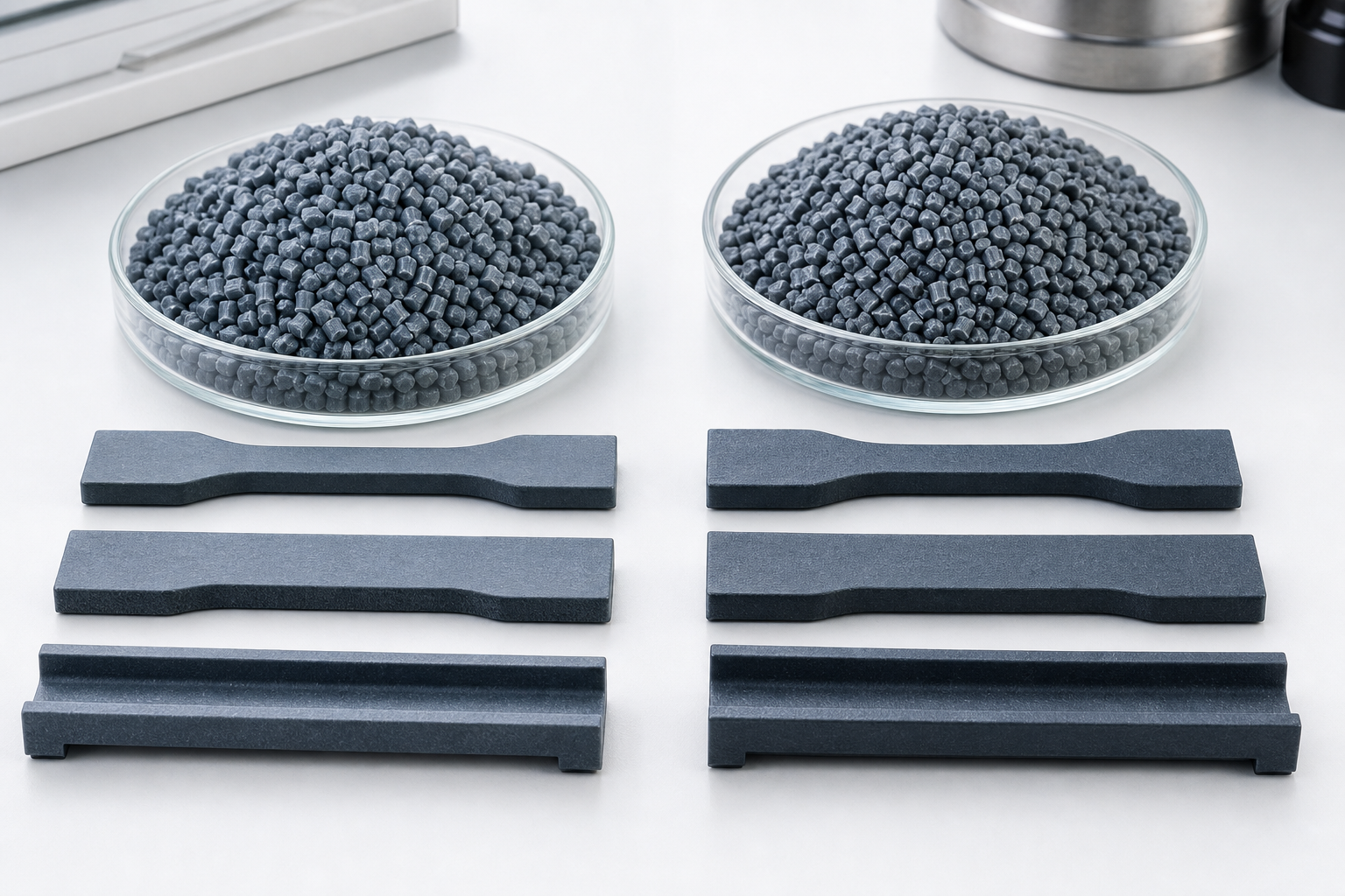
When engineers design structural components in automotive, industrial equipment, or electrical housings, the first question is often: “Where do I find the datasheet for PA66 GF30?” And the second question usually follows within minutes: “Should I use GF50 instead?”
PA66 reinforced with 30% or 50% glass fiber represents two of the most widely specified engineering thermoplastics in the world. Both offer the heat resistance of polyamide 66 combined with the dramatic stiffness and strength improvements that glass fiber reinforcement delivers. But the numerical gap — 30% vs 50% — does not translate linearly to performance, and assuming “more glass is always better” leads to tooling surprises, warpage problems, and cost overruns.
This article consolidates the key datasheet values for PA66 GF30 and GF50 in one place, explains what each property means in practical design terms, maps out the major commercial grades from BASF, DuPont, and DSM, and gives you a clear decision framework for choosing between them.
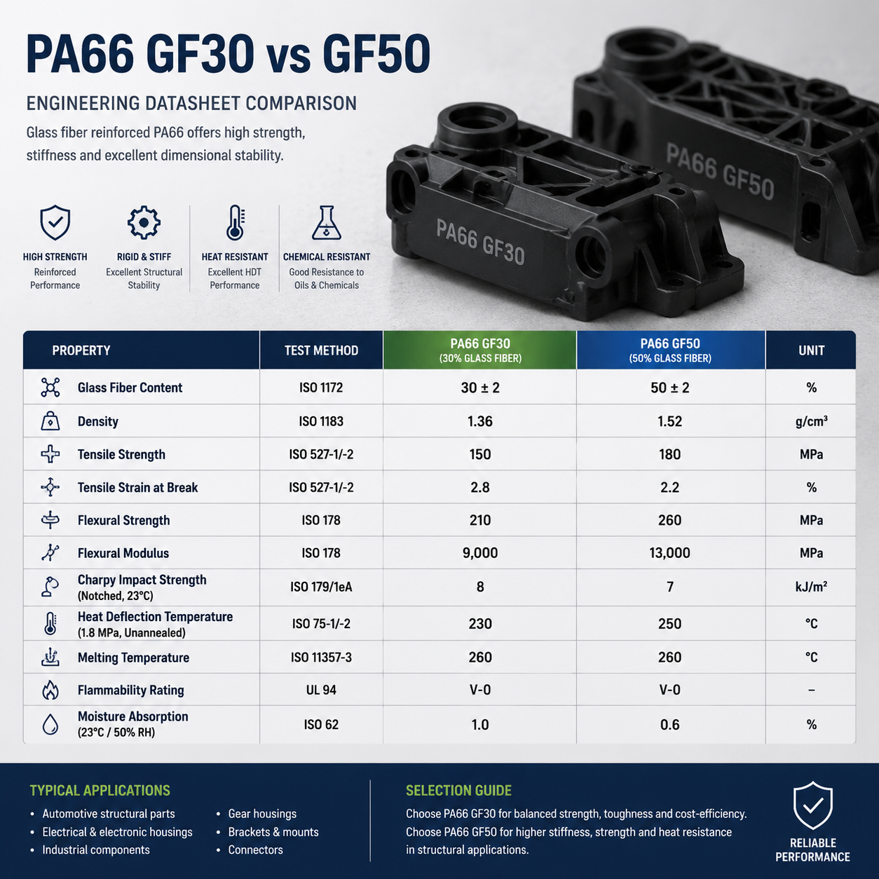
Quick Comparison Table: PA66 GF30 vs GF50 Datasheet Values
The values below represent typical injection molded specimens tested at 23°C in the dry-as-molded condition (DAM). Always consult the specific grade datasheet for your selected material, as formulation differences — heat stabilization, impact modification, lubricant packages — can shift individual properties by 5–15%.
| Eigendom | Eenheid | PA66 GF30 | PA66 GF50 | Testmethode |
|---|---|---|---|---|
| Dichtheid | g/cm³ | 1.35 – 1.38 | 1.55 – 1.58 | ISO 1183 |
| Tensile Strength (Break) | MPa | 180 – 195 | 220 – 240 | ISO 527 |
| Trekmodulus | MPa | 9,500 – 10,500 | 16,000 – 17,500 | ISO 527 |
| Buigsterkte | MPa | 270 – 290 | 340 – 370 | ISO 178 |
| Flexural Modulus | MPa | 8,500 – 9,200 | 14,000 – 15,500 | ISO 178 |
| Charpy-slagproef met inkeping (23 °C) | kJ/m² | 10 – 13 | 14 – 17 | ISO 179/1eA |
| Charpy Notched Impact (−30°C) | kJ/m² | 7 – 9 | 10 – 13 | ISO 179/1eA |
| HDT (1,8 MPa) | °C | 245 – 250 | 250 – 255 | ISO 75-2/Af |
| Melting Point (DSC) | °C | 255 – 265 | 255 – 265 | ISO 11357 |
| Mold Shrinkage (Flow) | % | 0.30 – 0.55 | 0.15 – 0.30 | ISO 294-4 |
| Mold Shrinkage (Transverse) | % | 0.60 – 0.90 | 0.35 – 0.55 | ISO 294-4 |
| Surface Resistivity | Ω | 10¹² – 10¹³ | 10¹² – 10¹³ | IEC 60093 |
What Each Property Means in Practice
Tensile Strength and Modulus: The Core Stiffness Numbers
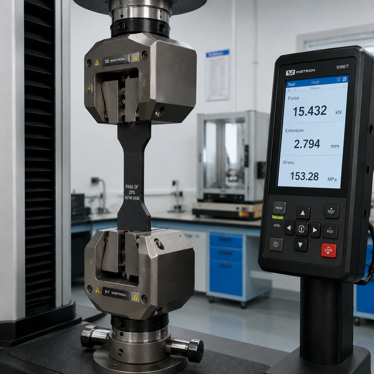
Tensile strength is the maximum stress the material can withstand while being pulled before it breaks. The jump from GF30 (approximately 185 MPa) to GF50 (approximately 230 MPa) represents a roughly 25% increase in ultimate strength. However, the tensile modulus — the material’s resistance to elastic deformation — nearly doubles. GF50 is dramatically stiffer: it stretches less under a given load. This matters for structural brackets, pump housings, and any application where deflection under load is the limiting design criterion rather than ultimate failure.
A practical consequence: if you are replacing die-cast aluminium with PA66, GF50 comes much closer to matching the stiffness of light metals. GF30 often requires ribbing or thicker wall sections to achieve equivalent structural rigidity.
HDT: Heat Deflection Under Load
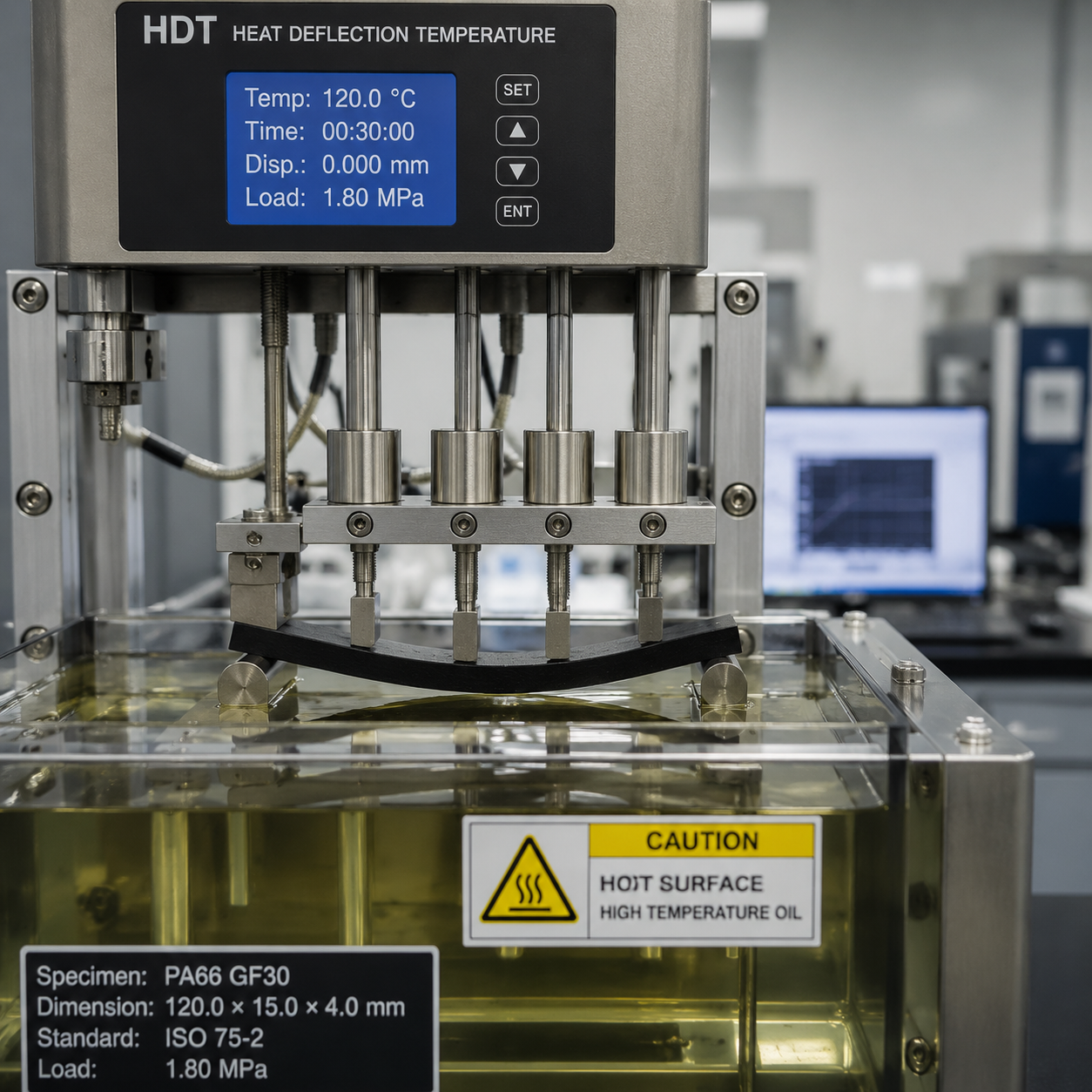
The HDT at 1.8 MPa (ISO 75-Af) for both GF30 and GF50 sits in the 245–255°C range — close to the crystalline melting point of PA66 itself. The glass fibers create a rigid skeletal network that resists deformation even as the PA66 matrix softens. The 5°C advantage GF50 holds at the upper end is real but small. In practice, both grades are rated for similar continuous-use temperature windows. The HDT value confirms that short-term exposure to 240°C+ is feasible, but above 220°C oxidative degradation of the polyamide matrix accelerates regardless of glass content.
Shrinkage and Warpage: The Hidden Differentiator
This is where the GF30 vs GF50 decision gets interesting. GF30 exhibits mold shrinkage of 0.3–0.55% in the flow direction and 0.6–0.9% transverse — a roughly 2:1 anisotropy ratio. GF50 shrinks less overall (0.15–0.3% flow, 0.35–0.55% transverse), and the anisotropy ratio tightens to approximately 1.7:1.
Lower absolute shrinkage means GF50 molds closer to nominal dimensions. But higher glass content also means higher melt viscosity, which requires higher injection pressures and can increase residual stress if the part has abrupt wall thickness transitions. For large, flat parts, GF50’s lower and more isotropic shrinkage is a genuine advantage. For thin-walled parts with long flow paths, GF30 may fill more easily and warp less in practice despite the higher datasheet shrinkage numbers.
Verwerkingsoverwegingen
GF50 demands more from the molding process: higher barrel temperatures (290–310°C recommended vs 280–300°C for GF30), higher injection pressures, and faster screw wear. Standard nitrided screws will wear noticeably faster processing GF50; bimetallic screws and barrels are strongly recommended for sustained production. Gate design matters more with GF50 because the higher viscosity and fiber content increase the risk of jetting and poor knit-line strength.
Conditioned vs Dry: The Moisture Effect
Polyamide 66 absorbs moisture from the environment — typically 1.5–2.5% by weight at equilibrium in 50% RH air. This absorbed water acts as a plasticizer, reducing stiffness and strength but dramatically increasing toughness. The table below shows typical property shifts from dry-as-molded (DAM) to equilibrium at 23°C / 50% RH.
| Eigendom | Eenheid | GF30 Dry | GF30 Cond. | GF50 Dry | GF50 Cond. |
|---|---|---|---|---|---|
| Treksterkte | MPa | 185 | 120 | 230 | 155 |
| Trekmodulus | MPa | 10,000 | 6,800 | 17,000 | 11,500 |
| Charpy Notched (23°C) | kJ/m² | 12 | 18 | 15 | 22 |
| Charpy Notched (−30°C) | kJ/m² | 8 | 7 | 12 | 10 |
| Flexural Modulus | MPa | 9,000 | 5,800 | 15,000 | 10,000 |
Two observations stand out. First, the property loss from moisture absorption is significant for both grades — tensile strength drops roughly 35% and modulus approximately 32% whether you start at GF30 or GF50. Second, and critically, the conditioned GF50 still outperforms dry GF30 in modulus (11,500 vs 10,000 MPa) and tensile strength (155 vs 185 MPa — roughly comparable). This means that in a humid application environment, the practical stiffness advantage of GF50 over GF30 narrows but does not disappear.
Commercial Grades and Equivalents
Most PA66 GF30 and GF50 grades on the market are formulated around a standard set of reference products. If your datasheet lists one of the grades below, the properties in this guide should align closely. For cross-referencing, always verify the specific additive package — heat-stabilized (H), impact-modified, or lubricated variants shift individual values.
| Supplier | PA66 GF30 Grade | PA66 GF50 Grade |
|---|---|---|
| BASF Ultramid | A3EG6 (standard), A3EG7 (35%) | A3EG10 |
| DuPont Zytel | 70G30HSL, 70G30HSLR | 70G50HSLR |
| DSM Akulon | K224-G6, S223-G6 | K224-G10, S223-G10 |
| Radici Radilon | A RV300 | A RV500 |
| Domo Technyl | A 218 V30 | A 218 V50 |
| Ascend Vydyne | R533, R533H | R550 |
BASF’s A3EG6 (GF30) and A3EG10 (GF50) are the most commonly cross-referenced grades worldwide. DuPont’s 70G30HSLR and 70G50HSLR add heat stabilization and lubricant for reduced mold deposit. DSM’s Akulon S223 series targets injection molding with excellent surface finish; the K224 variants are formulated for higher flow. If your application requires UL certification, grades with the “H” suffix from BASF and DuPont carry UL94 HB or V-2 listings by default and V-0 with additional flame-retardant packages.
When to Choose GF50 Over GF30
The decision often comes down to three engineering scenarios where the premium for higher glass loading pays for itself:
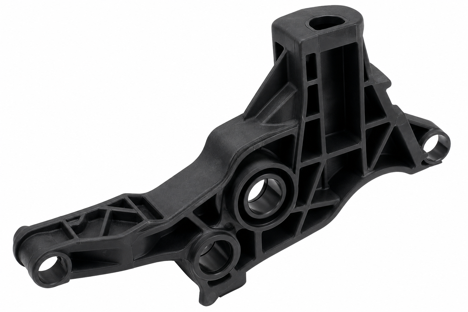
Scenario 1: Metal replacement where stiffness is non-negotiable. When your design is drop-in replacing a die-cast aluminum or stamped steel bracket and the existing wall thickness budget is fixed, GF30 may deflect unacceptably. GF50’s modulus of 16,000–17,500 MPa gets you into the stiffness territory of magnesium alloys. The weight savings over metal remain substantial — GF50 is still roughly one-quarter the density of aluminium.
Scenario 2: High-temperature structural load at elevated humidity. Components inside engine bays, turbocharger ducting, or industrial pump housings see both heat and moisture. As shown in the conditioned properties table, GF50 retains approximately 11,500 MPa modulus at equilibrium moisture — still above dry GF30. If your FEA model uses conditioned properties and shows marginal safety factors with GF30, stepping to GF50 is the most direct fix without redesigning geometry.
Scenario 3: Tight dimensional window with low post-mold movement. Parts that must hold precision tolerances across seasonal humidity cycles benefit from GF50’s lower absolute shrinkage and reduced moisture-induced dimensional change. Automotive sensor housings, electronic connector bodies, and precision gear carriers are classic examples.
When to Stay with GF30
GF30 remains the right choice when: your mold already exists and was cut for GF30 shrinkage (retrofitting is expensive); the part has thin walls under 1.5 mm where GF50 might short-shot; you need better surface aesthetics (lower glass content gives smoother as-molded surfaces); or the cost delta matters — GF50 typically commands a 15–25% price premium per kilogram, and molded part weight is also roughly 15% higher due to density.
PA66 Glass Fiber Grade Comparison: GF15 to GF60
While this guide focuses on the GF30 vs GF50 decision, the broader PA66 GF family includes five common glass fiber loadings. The table below provides screening values across all grades so you can see where GF30 and GF50 sit in the full performance spectrum.
| Eigendom | PA66 zonder vulstof | PA66 GF15 | PA66 GF30 | PA66 GF40 | PA66 GF50 | PA66 GF60 |
|---|---|---|---|---|---|---|
| Tensile Strength (MPa, dry) | 75 – 85 | 140 – 160 | 180 – 200 | 200 – 220 | 220 – 240 | 235 – 255 |
| Flexural Modulus (MPa) | 2,800 – 3,200 | 5,500 – 7,000 | 8,500 – 10,000 | 11,500 – 13,500 | 14,000 – 17,000 | 17,000 – 20,000 |
| Rek bij breuk (%) | 20 – 50 | 3 – 5 | 3 – 4 | 2 – 3 | 1.5 – 2.5 | 1 – 2 |
| Charpy Notched Impact (kJ/m², 23°C) | 5 – 8 | 9 – 12 | 10 – 14 | 12 – 15 | 14 – 17 | 15 – 18 |
| Dichtheid (g/cm³) | 1.13 – 1.15 | 1.22 – 1.25 | 1.36 – 1.38 | 1.44 – 1.48 | 1.55 – 1.58 | 1.65 – 1.70 |
| HDT/A, 1.8 MPa (°C) | 65 – 85 | 200 – 220 | 245 – 255 | 250 – 258 | 252 – 260 | 255 – 262 |
| Mold Shrinkage — Flow (%) | 1.2 – 1.8 | 0.5 – 0.8 | 0.3 – 0.55 | 0.2 – 0.4 | 0.15 – 0.30 | 0.10 – 0.25 |
| Mold Shrinkage — Transverse (%) | 1.2 – 1.8 | 0.7 – 1.0 | 0.6 – 0.9 | 0.5 – 0.7 | 0.35 – 0.55 | 0.25 – 0.45 |
| Typical Use Case | Clips, non-structural | Medium-stiffness brackets | Radiator tanks, connectors, structural brackets | Pump bodies, high-load frames | Metal replacement, load-bearing | Maximum stiffness, specialized metal substitution |
Where GF30 fits in the family: GF30 is the most balanced grade in the PA66 GF family. It provides a roughly 2.5× stiffness increase over unfilled PA66 while retaining enough impact toughness for structural applications. GF15 saves cost where full GF30 stiffness is unnecessary. GF40 and GF50 progressively increase stiffness at the cost of elongation and processing ease. GF60 is a specialized maximum-stiffness grade typically reserved for metal-substitution projects where every MPa of modulus is justified by weight reduction or corrosion elimination.
PA66 GF30 Injection Molding Processing Parameters
| Parameter | PA66 GF30 Range | Opmerkingen |
|---|---|---|
| Pre-drying Temperature | 80 – 90°C | Desiccant dryer required. Moisture must be <0.10% before molding. |
| Pre-drying Time | 4 – 6 hours | Longer for material exposed to ambient air >30 minutes. |
| Smelttemperatuur | 275 – 300°C | Stay within supplier’s recommended window. Higher temps risk degradation. |
| Schimmel Temperatuur | 80 – 110°C | Higher mold temp improves crystallinity, surface finish, and dimensional stability. Use mold temperature controller. |
| Injectiedruk | 80 – 140 MPa | Adjust for cavity filling. Higher pressure improves knit-line strength. |
| Druk vasthouden | 50 – 80% of injection pressure | Compensates for glass-filled shrinkage. Adequate hold time prevents sink marks. |
| Tegen druk | 3 – 8 MPa | Moderate back pressure helps fiber dispersion. Excessive back pressure shears fibers. |
| Schroefsnelheid | 40 – 80 rpm | Slower speeds reduce fiber breakage. Use wear-resistant screw and barrel. |
| Type poort | Direct, fan, or tab gate preferred | Avoid pin gates for structural parts. Gate location controls fiber orientation. |
| Residual Moisture (max) | 0.10% (1,000 ppm) | Verify with moisture analyzer before production start. |
Belangrijke opmerkingen over de verwerking: PA66 GF30 is abrasive — tool steel selection matters for production molds exceeding 50,000 shots. Hardened steel (H13, S136) or hard-chrome-plated cavities are preferred. Use Moldflow simulation before cutting steel to predict fiber orientation, weld line positions, and warpage. Fiber orientation follows flow direction: orient gates so that fiber alignment coincides with the primary load path. Avoid placing weld lines at mounting bosses or pressure-sealing surfaces.
Veelgestelde vragen
Wat is het verschil tussen PA66 GF30 en PA6 GF30?
PA6 GF30 heeft een lager smeltpunt (ongeveer 220 °C tegenover 260 °C voor PA66) en een lagere HDT (doorgaans 200–210 °C bij 1,8 MPa tegenover 245–250 °C). Ook de treksterkte is lager — PA6 GF30 haalt doorgaans 160–180 MPa tegenover 180–195 MPa voor PA66 GF30. PA6 GF30 is echter gemakkelijker te verwerken, vloeit beter in dunne wanden en heeft een mooier oppervlak. PA6 neemt ook iets sneller vocht op. Kies PA66 GF30 wanneer hittebestendigheid onder structurele belasting de prioriteit is; kies PA6 GF30 voor grote cosmetische onderdelen of wanneer het verwerkingsvenster krap is.
Welk matrijsstaal is nodig voor de productie van PA66 GF50?
PA66 GF50 is abrasive due to the high glass fiber content. For prototype or low-volume tools (under 50,000 shots), hardened P20 or 718 steel with nitriding is acceptable. For production volumes above 50,000 cycles, H13 or 1.2344 tool steel hardened to 48–52 HRC is recommended. Gate inserts and runner systems wear fastest; using replaceable inserts with D2 or M2 tool steel at high-wear points extends tool life. Venting depth should be limited to 0.01–0.02 mm to prevent flash with GF50’s low melt viscosity at processing temperatures.
Kunnen PA66 GF30 en GF50 met een laser worden gemarkeerd?
Ja, maar de resultaten lopen sterk uiteen. Natuurlijke (ongekleurde) PA66 GF-kwaliteiten kunnen met een Nd:YAG- of vezellaser worden gelasermarkeerd, waarbij een donkere markering op een lichte achtergrond ontstaat — de laser verkolt het polyamideoppervlak. De glasvezels aan het oppervlak verstrooien de laserstraal echter, waardoor het contrast afneemt. GF30 levert een beter contrast bij lasermarkering op dan GF50, omdat het hogere harsgehalte aan het oppervlak meer organisch materiaal biedt voor verkoling. Voor GF50 worden lasergevoelige additieven of een vooraf samengestelde, lasermarkeerbare kwaliteit (op aanvraag verkrijgbaar bij de meeste grote leveranciers) aanbevolen voor betrouwbare markering met een hoog contrast.
Wat is de maximale temperatuur bij continu gebruik voor PA66 GF30 en GF50?
There is no single number — it depends on the specific failure criterion. For mechanical load-bearing applications: approximately 120–140°C for GF30 and 130–150°C for GF50 when the load is moderate (under 30% of ultimate tensile strength). For purely thermal exposure without mechanical load: UL Relative Thermal Index (RTI) ratings are typically 130–140°C for both grades when heat-stabilized. Short-term excursions to 180–200°C are acceptable for minutes rather than hours. Above 220°C, oxidative degradation accelerates sharply and service life is measured in hours regardless of glass content. Heat-stabilized variants (suffix “H” or “HS”) extend the thermal aging resistance by 15–25°C over standard grades.
Gerelateerde lezen
- Handleiding voor langketenige nylonsoorten PA11 en PA12
- Stanyl PA46 High-Temperature Nylon Guide
- Recycled Nylon RPA and PCR Content Guide
Request a PA66 GF30 or GF50 Grade Review
Review the PA66 material guide of nylon injection molding services, then use the form below to request the matching datasheet, sample or quotation.