
Plastic rollers manufacturer selection should begin with the load path, shaft or bearing layout, operating speed and allowable runout, not with a resin name alone. A qualified drawing lets the supplier manufacture conveyor rollers, idlers, guide rollers, wheels and sheaves around the actual assembly rather than quoting an isolated cylinder.
For a useful quotation, define what the roller touches, how it is supported, how long it runs, what causes failure today and which dimensions control machine performance. This prevents an inexpensive material choice from creating bearing creep, tracking problems, product marks or premature replacement.
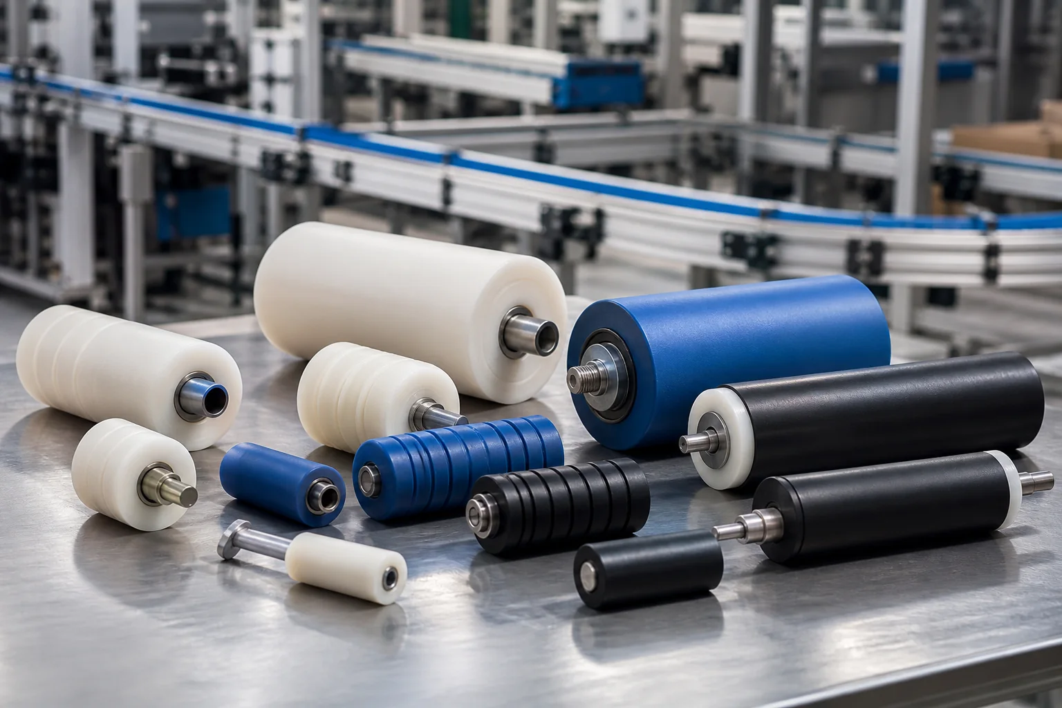
For conveyor, packaging and industrial equipment buyers
Roller Specification Brief
Define first: load, speed, duty cycle, shaft span and the component contacting the roller.
Control next: bearing seats, bore, outside diameter, face geometry, runout and surface condition.
Choose last: material grade, stock form and CNC, molding or covered-roller route.
Start With the Load Path, Not the Plastic Name
A roller can carry a radial product load, guide a belt edge, transmit torque, tension film or simply reduce sliding friction. Each function creates a different failure mode. A long idler may be governed by deflection, while a compact drive roller may be governed by hub stress, bearing fit or traction. Flanges and grooves can receive concentrated side loads that are not visible in the nominal radial-load figure.
Share the worst operating case as well as the normal cycle. Start-stop motion, impact, product accumulation, washdown heat and an overtightened belt can control design even when average speed is low. If a current part fails, photographs and the failed sample often reveal more than a material name on an old drawing.
Choose the Roller Architecture Before Assigning Tolerances
| Roller Architecture | Typical Function | Buyer Details to Confirm |
|---|---|---|
| Plain bore roller | Shaft is fixed or rotates inside the bore | Bore clearance, shaft finish, lubrication and edge loading |
| Press-fit bearing roller | Replaceable rolling bearings support speed and alignment | Bearing fit, shoulder support, press method and operating temperature |
| Shaft-mounted assembly | Roller, hub and shaft are supplied as one reviewed assembly | Retention method, shaft material, end features and service access |
| Flanged or grooved roller | Guides belt, cable, film, product or rail | Groove profile, flange load, tracking error and edge radius |
| Crowned or covered roller | Controls tracking or adds traction and product protection | Crown amount, cover hardness, bond system and allowable runout |
The bearing or shaft arrangement establishes the functional datum. When runout matters, the drawing should relate the outside diameter and groove or crown to the bore, bearing seats or installed shaft. Applying close tolerance independently to every diameter increases inspection cost without guaranteeing better tracking.
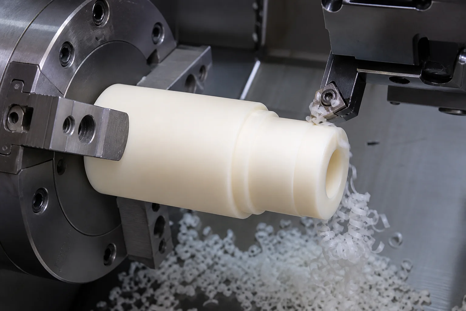
Material Direction by Roller Duty
| Material Direction | Common Starting Point | Design Caution |
|---|---|---|
| Nylon or cast nylon | Loaded rollers, sheaves and noise-sensitive handling | Good toughness and wear potential; account for moisture, creep and thermal movement |
| POM / acetaal | Precision guide, idler and packaging rollers | Low moisture uptake and stable machining; verify impact, chemical and temperature duty |
| UHMW-PE | Low-friction, impact and product-contact guidance | Excellent sliding behavior but lower stiffness can increase deflection and runout |
| PEEK | High-temperature or chemically demanding equipment | High performance at premium material cost; confirm the exact grade and business case |
| Elastomer-covered core | Traction, cushioning or mark-sensitive transport | Specify core, cover chemistry, hardness, thickness, bond and regrind allowance |
Material data sheets are screening tools, not service-life guarantees. Wear depends on pressure, speed, alignment, counterface roughness, debris and lubrication. Food, medical, electrical or other regulated uses also require the buyer to identify the exact compliance document and grade; a base polymer family does not make every color or formulation compliant.
Bearing, Shaft and Surface Decisions
- Bearing interface: identify bearing part number, fit objective, shoulder, spacer, seal and replacement method.
- Shaft interface: state whether the shaft rotates, whether torque is transmitted and how axial movement is controlled.
- Runout datum: connect outside diameter, grooves and flanges to the installed rotational axis.
- Contact surface: define finish, crown, groove, edge radius, traction and whether product marking is acceptable.
- Environment: include temperature, humidity, immersion, cleaners, oils, UV, dust and abrasive contamination.
- Maintenance: explain lubrication, cleaning, expected replacement interval and field access.
A press fit that works in a thick, dry acetal hub may not work in a thin nylon wall exposed to warm water. Likewise, a very soft or low-friction material may protect products but deflect too much for precision tracking. These interfaces should be reviewed as an assembly rather than as separate catalogue items.
Common Roller Problems and Corrective Actions
| Observed Risk | Waarschijnlijke oorzaak | Practical Corrective Action |
|---|---|---|
| Excessive radial runout | The bore, bearing seats and outside diameter were finished from unrelated setups | Define the functional datum and finish critical diameters in a controlled setup where practical |
| Bearing moves in the bore | Fit, temperature or polymer creep was not reviewed | Select bearing fit from grade, wall thickness, heat and service load; add shoulders or retention when required |
| Roller bends or develops a flat | Face width, wall section or storage load exceeds material stiffness | Check shaft span and roller deflection, then increase section or choose a stiffer construction |
| Product tracks to one side | Crown, groove, shaft alignment or frame geometry is incorrect | Review the complete conveyor geometry instead of adjusting roller diameter alone |
| Dimensions change after installation | Moisture or temperature differs from inspection conditions | State service conditions and agree on material conditioning and functional clearance |
| Surface damages the conveyed product | Finish, edge break or embedded debris was not controlled | Specify surface condition, cleaning, packaging and contact-edge requirements |
CNC Machining, Molding or Built-Up Construction?
CNC machining is the usual starting route for prototypes, replacement parts, low-to-medium quantities and rollers with bearing seats, grooves or revision-sensitive geometry. Tube or near-net stock can improve material yield for larger diameters. A built-up design using a plastic shell, metal shaft or replaceable bearing may outperform a one-piece roller when stiffness and maintenance are important.
Injection molding can lower unit cost when annual demand is stable and the geometry supports repeatable shrinkage, gating and ejection. The tooling case should include validation, material conditioning, inserts and expected design changes. Covered rollers require a separate review of core preparation, elastomer chemistry, hardness, bond and final grinding.

Related Engineering Resources
- Nylatron Machining Services for Industrial Wear Parts
- Op maat vervaardigde kunststof onderdelen
- Plastic Bearing Materials and Self-Lubricating Grades
- CNC Plastic Milling Services
Veelgestelde vragen
What information does a plastic rollers manufacturer need for a quote?
Provide a drawing or sample, outside diameter, face width, bore or bearing data, shaft arrangement, load, speed, duty cycle, environment, runout requirement, quantity and annual demand.
Is nylon or acetal better for a custom plastic roller?
Nylon often suits tougher or more heavily loaded wear applications, while acetal often favors dimensional stability and lower moisture uptake. The correct choice depends on load, speed, environment, geometry and mating surfaces.
Can bearings be press-fitted into a plastic roller?
Yes, but the fit must account for polymer creep, wall thickness, temperature, moisture and press stress. A metal-style interference fit should not be copied without review.
How is roller runout controlled?
Control starts with a functional datum plan linking the bore or bearing seats to the outside diameter. Workholding, staged machining, inspection setup and material stability also affect the result.
Should a custom roller be CNC machined or molded?
CNC machining is usually practical for prototypes, low-to-medium volumes and changing designs. Molding can reduce unit cost at stable higher volumes after geometry, material and tooling economics are validated.
Request a Custom Plastic Roller Review
For a guide, idler, driven or product-contact roller, send the roller and shaft drawings with the bearing arrangement and operating duty. Nylon Plastic has supported material selection and custom manufacturing since 2005; the review connects the roller body, installed axis, contact surface and inspection requirements.
Wat moet je in je verzoek vermelden?
- Geometry: 2D drawing and 3D model with outside diameter, face width, grooves, flanges, crown and edge details.
- Support: shaft drawing, bearing part number, housing arrangement, span and retention method.
- Duty: radial and axial load, line speed, RPM, start-stop frequency, shock and daily operating hours.
- Performance: runout, concentricity, balance, surface finish, traction and product-marking limits.
- Environment: service temperature, moisture, washdown, chemicals, UV, dust and cleanliness requirements.
- Quantity and timing: prototype quantity, batch quantity, annual demand, target replacement interval and delivery schedule.
- Material and approval: exact grade or permitted alternative; installed runout datum, bearing-fit and rotation check, traction or marking reference, inspection report, destination and packaging. For material-only selection, identify the current grade and exposure.
Confirm whether the quote covers a roller body, a covered core or a complete unit with shaft, bearings, seals and retention hardware. Separate any requested covering or bonding, machining or tooling, assembly, inspection and packaging. Provide production-intent mating parts for sample approval where needed; a diameter reading alone does not establish tracking, traction or acceptable product marking. Agree any load, rotation or balance test and its responsibility.

