
Inleiding tot het ontwerpen van spuitgietmatrijzen
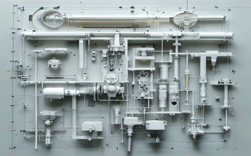
Het ontwerp van een spuitgietmatrijs is de basis voor de succesvolle productie van kunststof onderdelen. Een goed ontworpen matrijs garandeert een consistente productkwaliteit, efficiënte productiecycli en een lange levensduur van de matrijs. Deze gids behandelt de essentiële principes die elke ingenieur moet begrijpen.
1. Uniforme wanddikte
Een consistente wanddikte is essentieel bij spuitgieten. Variaties veroorzaken verschillende koeling, wat leidt tot kromtrekken, zinkvlekken en inwendige spanningen.
Aanbevolen wanddikte per materiaal
| Materiaal | Aanbevolen dikte (mm) |
|---|---|
| ABS | 1.2 - 3.5 |
| PP | 0.8 - 3.8 |
| PC | 1.0 - 3.8 |
| Nylon (PA6/PA66) | 0.8 - 3.0 |
| POM | 1.0 - 3.0 |
2. Ontwerphoeken voor het vrijgeven van onderdelen
Dankzij trekhoeken kunnen spuitgietproducten netjes uit de matrijsholte komen. Zonder voldoende trek kunnen onderdelen blijven kleven en defecten en schade aan de matrijs veroorzaken.
- Minimale diepgang: 0,5° - 1° voor gladde oppervlakken
- Oppervlakken met structuur: 2° - 5° afhankelijk van textuurdiepte
- Diepe functies: Verhoog de trekkracht om materiaalkrimp te compenseren
3. Juist ribontwerp
4. Strategie voor poortlocatie
De plaatsing van de poort beïnvloedt het vulpatroon, de laslijnen en het uiterlijk van het onderdeel. Overweeg:
- Stromingslengte: Minimaliseren om drukval te verminderen
- Plaatsing van laslijnen: Positie in niet-kritieke gebieden
- Uiterlijk: Verberg waar mogelijk hekken in niet-zichtbare ruimtes
- Deelfunctie: Vermijd hekken in de buurt van dragende elementen
5. Ontwerp koelsysteem
Efficiënt koelen verkort de cyclustijd en verbetert de kwaliteit van de werkstukken. Belangrijkste overwegingen:
- Gelijkmatige afstand tussen koelkanalen (2-3× kanaaldiameter)
- Baffles en bubblers voor diepe kernen
- Conformale koeling voor complexe geometrieën
- Juiste waterstroomsnelheid (turbulent stromingsregime)
Veelvoorkomende ontwerpfouten die je moet vermijden
- Ondersnijdingen zonder goed mechanisme (hefarmen, geleiders)
- Scherpe interne hoeken die spanningsconcentratie veroorzaken
- Onvoldoende ontluchting leidt tot verbranding en korte schoten
- Het negeren van materiaalkrimp in maatberekeningen
Conclusie
Het volgen van deze ontwerpprincipes voor spuitgietmatrijzen zorgt voor produceerbare onderdelen met een consistente kwaliteit. Vroegtijdige samenwerking tussen productontwerpers en matrijsingenieurs voorkomt dure aanpassingen achteraf.
Verwante bronnen
- CNC Bewerking Nylon
- 3D printen voor prototyping vs productie
- Selectiegids voor kunststof materialen
- Technische plastic kostenfactoren
- Vergelijking PEEK vs PEI
Verwante bronnen
- CNC Bewerking Nylon
- 3D printen voor prototyping vs productie
- Selectiegids voor kunststof materialen
- Technische plastic kostenfactoren
- Vergelijking PEEK vs PEI
Verwante bronnen
- CNC Bewerking Nylon
- 3D printen voor prototyping vs productie
- Selectiegids voor kunststof materialen
- Technische plastic kostenfactoren
- Vergelijking PEEK vs PEI
FAQ
When does Injection Mold Design Principles — Building Quality Molds from the Ground Up make sense?
Injection Mold Design Principles — Building Quality Molds from the Ground Up makes sense when the part volume, material choice, geometry, and repeatability needs justify mold design and tooling investment.
What design factors matter most for Injection Mold Design Principles — Building Quality Molds from the Ground Up?
Wanddikte, ribben, uitsteeksels, uitloophoek, plaats van de ingietopening, krimp, scheidingslijn en uitwerping zijn allemaal van invloed op de kwaliteit van het spuitgietdeel.
Welke informatie is nodig vóór de productie van mallen?
De leverancier dient het 3D-model, het materiaal, het verwachte jaarlijkse volume, de eisen ten aanzien van het uiterlijk, de tolerantie-eisen en eventuele eisen met betrekking tot montage of functionele tests te bevestigen.
What is the biggest risk in Injection Mold Design Principles — Building Quality Molds from the Ground Up?
Het grootste risico is dat de matrijzen worden goedgekeurd voordat het gedrag van het materiaal, de krimp, de vloei en de werking van het onderdeel volledig zijn getoetst aan de daadwerkelijke toepassing.
How to Review an Injection Mold Design Before Steel
A good mold design review connects the molded part to the actual production machine, resin, cycle, inspection method and expected tool life. A drawing can look complete while still leaving important decisions open: where the gate will be placed, how air will leave the cavity, how the part will be released, how cooling will reach thick sections and how worn components will be replaced. Before steel is cut, ask for a review that explains these decisions in relation to your part requirements.
Start with the controlled part drawing and mark critical-to-function dimensions, sealing surfaces, assembly datums, cosmetic zones, inserts and areas that cannot show ejector marks or gate vestige. Add the resin grade, filler content, color, annual volume, target cycle and molding machine limits. These inputs determine whether a simple single-cavity tool, a multi-cavity tool, a family mold or a more automated solution is appropriate.
| Design area | Buyer risk | Evidence to request |
|---|---|---|
| Parting line and shutoffs | Flash, mismatch, sealing damage or an unacceptable cosmetic line | Parting-line mark-up, shutoff angles and sample standard |
| Gate and runner | Weld lines, air traps, poor packing, fiber orientation or visible vestige | Gate location, fill direction and runner-balance concept |
| Cooling layout | Long cycle, uneven shrinkage, sink, warpage or local overheating | Cooling circuit drawing and temperature-control assumptions |
| Ejection | Sticking, deformation, drag marks or pin witness on a critical surface | Ejector map, draft review and release-force plan |
| Maintenance access | Long downtime when wear parts or slides need service | Replaceable insert list, spare parts and service access |
Gate, Venting and Cooling Decisions
Gate location should follow the part’s functional and cosmetic priorities. A gate near a thick section may improve packing but can increase sink or vestige. A gate on a cosmetic face may shorten flow length but create an appearance problem. For glass-filled resin, the flow direction can influence stiffness, shrinkage and anisotropy. Multi-cavity tools also need a balanced runner system so each cavity receives a consistent melt history.
Venting is part of the filling design, not a late repair. End-of-fill areas, deep ribs, blind pockets, slides and weld-line regions need a practical escape path for air and gas. Inadequate venting can show up as burn marks, short fill, gloss differences or unstable filling. Ask how vents will be machined, cleaned and protected during maintenance.
Cooling should cover thick bosses, ribs, inserts and areas near the gate while keeping sufficient steel around the cavity. The circuit should be reachable for cleaning and leak checks. Baffles, bubblers or conformal channels may be considered when conventional drilling cannot control temperature. The best choice depends on cycle target, part geometry, steel layout and the value of reducing dimensional variation.
Tool Architecture and Steel Selection
Tool architecture should match volume and resin severity. Prototype and low-volume programs often benefit from accessible inserts and a design that can be changed after the first trial. Higher-volume programs usually need robust cavity details, balanced cooling, reliable automation interfaces and serviceable wear components. For abrasive or corrosive materials, cavity steel, hardness, surface treatment and replaceable gates deserve a documented decision.
| Project condition | Design emphasis | Questions for the quotation |
|---|---|---|
| Prototype or pilot | Fast changes and accessible inserts | Which features can be adjusted after T1? |
| Repeat production | Cycle stability, balance and maintenance access | What shots, cycle and service interval are supported? |
| Abrasive engineering resin | Wear resistance at gates, slides and shutoffs | Which steel and spare inserts are included? |
| Tight cosmetic requirement | Gate, polish, texture, vent and parting-line control | What sample is used for appearance approval? |
Trial, Inspection and Tool Acceptance
A mold should be accepted against an agreed trial plan, not only because the machine produces a part. Record resin grade and lot, machine, mold temperature, melt temperature, injection profile, holding conditions, cycle and cavity identification. Review short shots, flash, sink, burn marks, weld lines, ejection, warpage and dimensions. For multi-cavity tools, inspect cavity-to-cavity variation instead of relying on one representative part.
Before production release, request the approved mold drawing, steel and component list, cooling and pneumatic diagrams, cavity identification, spare-parts list, maintenance instructions and dimensional report. Critical features should be measured with the agreed datum and conditioning state. If a dimension is affected by moisture or temperature, define when the measurement is taken. We can support DFM review, mold design, fabrication, sampling and corrective changes as one connected project.
For an RFQ, send CAD, controlled drawing, resin data, volume, target cycle, machine information, cosmetic zones, critical dimensions, inserts, post-molding assembly and required tests. A complete input package allows a mold supplier to price the actual risk rather than adding broad assumptions to the quotation.

