
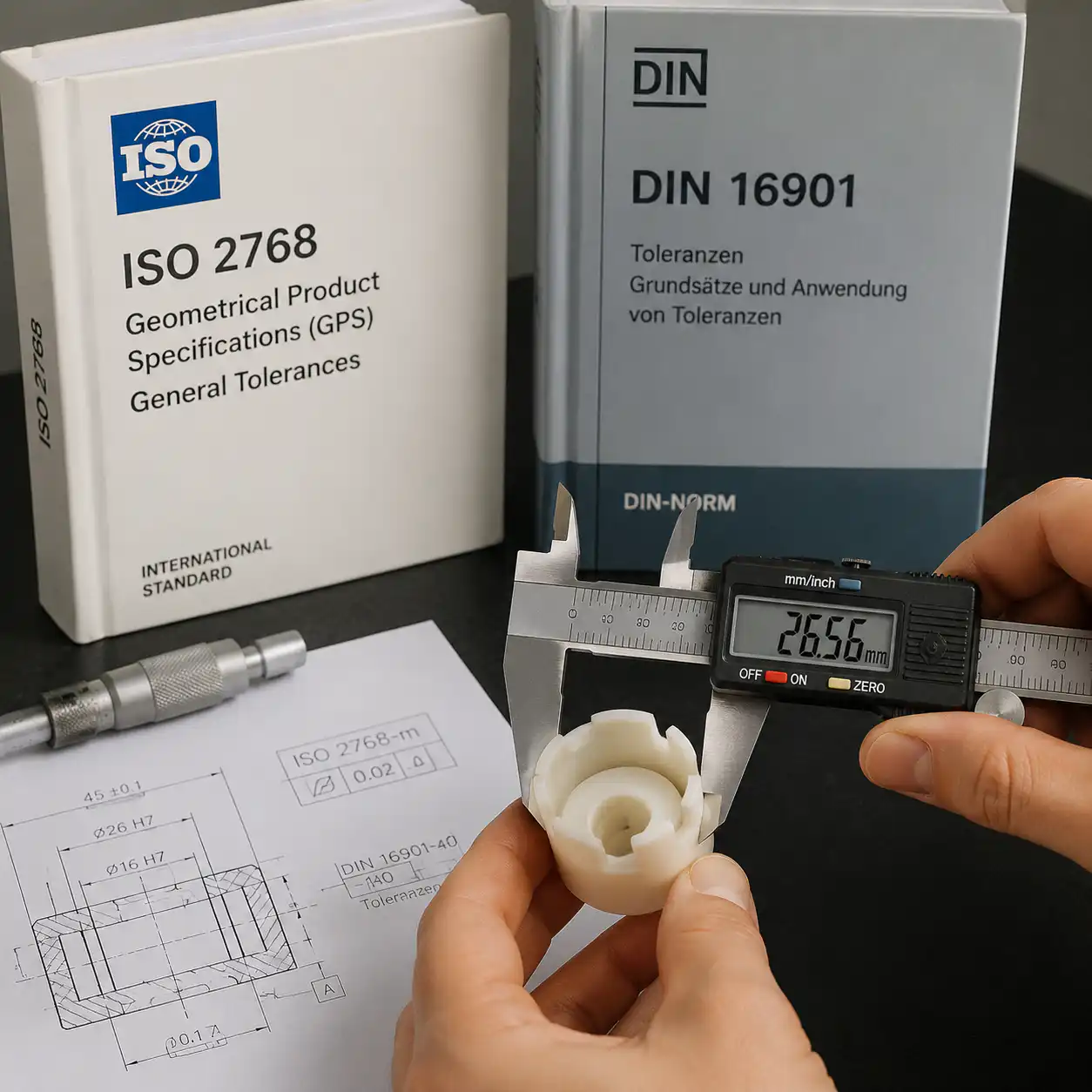
Dimensional tolerances are the silent make-or-break factor in every plastic injection molding project. A deviation of 0.05mm might be invisible to the eye, but it can mean the difference between a snap-fit that clicks perfectly and one that rattles loose. This comprehensive guide covers ISO 2768, DIN 16901, and the practical realities of achieving tight tolerances with engineering plastics.
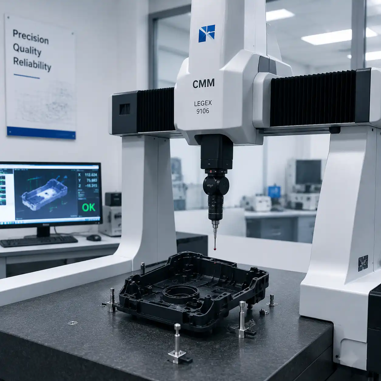
Dimensional tolerances are the silent make-or-break factor in every plastic injection molding project. A deviation of 0.05mm might be invisible to the eye, but it can mean the difference between a snap-fit that clicks perfectly and one that rattles loose. This comprehensive guide covers ISO 2768, DIN 16901, and the practical realities of achieving tight tolerances with engineering plastics.
Why Tolerances Matter in Plastic Parts
Unlike metals, thermoplastics shrink during cooling — and they shrink anisotropically, meaning differently in flow and cross-flow directions. Add glass fiber orientation, mold temperature gradients, and varying wall thickness, and you have a complex dimensional puzzle. Getting tolerances right affects assembly fit, sealing performance, aesthetic quality, and ultimately your rejection rate and total cost.
ISO 2768 General Tolerances for Plastics
ISO 2768 provides general tolerance classes for linear dimensions and angular dimensions where no specific tolerance is indicated on the drawing. For plastic parts, the relevant standard is ISO 2768-1 (linear and angular dimensions) with the mK tolerance class typically applied.
| Tolerance Class | 0.5–3mm | 3–6mm | 6–30mm | 30–120mm | 120–400mm | Typische toepassing |
|---|---|---|---|---|---|---|
| f (fine) | ±0.05 | ±0.05 | ±0.1 | ±0.15 | ±0.2 | Precision gears, optical |
| m (medium) | ±0.1 | ±0.1 | ±0.2 | ±0.3 | ±0.5 | Most injection molded parts |
| c (coarse) | ±0.2 | ±0.3 | ±0.5 | ±0.8 | ±1.2 | Low-precision housings |
| v (very coarse) | ±0.5 | ±1.0 | ±1.5 | ±2.0 | ±3.0 | Large non-critical parts |
For most engineering plastic parts, ISO 2768-m is a reasonable starting point. ISO 2768-f is achievable only with careful mold design, stable processing, and materials with predictable shrinkage.

DIN 16901 — Injection Molding Specific Tolerances
DIN 16901 is the gold standard for injection molding tolerances. Unlike ISO 2768, it accounts for material-specific shrinkage behavior by grouping thermoplastics into shrinkage categories. This makes it far more practical for mold makers and quality engineers.
| Materiaal | Shrinkage Group | Typical Shrinkage | Grade A (tight) | Grade B (standard) | Grade C (loose) |
|---|---|---|---|---|---|
| PA6/PA66 unfilled | Group 2 | 1.0–2.0% | ±0.1% | ±0.2% | ±0.4% |
| PA66 GF30 | Group 1 | 0.3–0.7% | ±0.05% | ±0.1% | ±0.2% |
| POM (acetaal) | Group 2 | 1.8–2.5% | ±0.1% | ±0.2% | ±0.4% |
| PC (polycarbonaat) | Group 1 | 0.5–0.7% | ±0.05% | ±0.1% | ±0.2% |
| ABS | Group 1 | 0.4–0.7% | ±0.05% | ±0.1% | ±0.2% |
| PP unfilled | Group 3 | 1.5–2.5% | ±0.2% | ±0.4% | ±0.6% |
Belangrijkste conclusie: Glass fiber reinforcement dramatically improves dimensional stability. PA66 GF30 (Group 1) can achieve tolerances nearly as tight as unfilled PC, while unfilled PA66 (Group 2) needs wider tolerance allowances due to higher and more variable shrinkage.
How Shrinkage Affects Achievable Tolerance
Shrinkage is the single largest variable in plastic part tolerances. Here is how different materials compare. If you need to predict how those shrinkage patterns will actually distort a cavity before steel is cut, our mold flow analysis and DFM guide shows how simulation is used in practice.
- Nylon 6/66 unfilled: 1.0–2.0% shrinkage. A 100mm dimension can vary by 1–2mm just from the material alone, before considering mold and process variation.
- Nylon 66 GF30: 0.3–0.7% in flow direction, 0.7–1.0% cross-flow. The glass fiber constrains shrinkage but creates anisotropy — dimensions differ depending on fiber orientation.
- POM: 1.8–2.5% — the highest shrinkage of common engineering plastics, which is why tight-tolerance POM parts need very precise mold compensation.
- PC: 0.5–0.7% — excellent dimensional stability, making it a preferred choice for optical and precision applications.
The mold maker must calculate cavity dimensions as: Nominal Dimension × (1 + Shrinkage Rate), then fine-tune after first-shot samples. Modern Moldflow simulation predicts shrinkage within ±0.1% accuracy when properly calibrated.
Tolerance Stack-Up Analysis
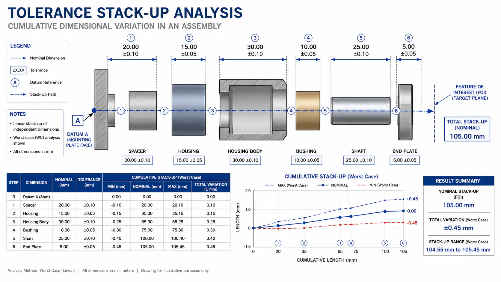
When multiple toleranced features interact in an assembly, their individual tolerances accumulate. The practical formula for worst-case stack-up is:
Ttotal = T1 + T2 + … + Tn
For statistical (RSS) stack-up, which is more realistic for production volumes:
Ttotal = √(T1² + T2² + … + Tn²)
Common mistakes include forgetting to account for the mold split line tolerance, ignoring thermal expansion differences between assembled materials, and treating shrink rates as constants rather than ranges. Always run a tolerance analysis before finalizing mold steel — it is far cheaper than discovering interference at first-shot inspection.
Design for Tolerance — Best Practices
Uniform wall thickness: The single most effective way to improve dimensional control. Thick-to-thin transitions cause differential cooling and warpage.
Locatie van de poort: Position the gate so the melt front fills the cavity uniformly, minimizing anisotropic shrinkage. A poorly placed gate creates asymmetric flow patterns that warp the part. Our gate design guide explains how gate type and location drive this behavior.
Mold steel selection: For tight tolerances (±0.02mm or better), use hardened tool steel (H13, S136) rather than P20. Hardened steel holds dimensions longer and provides better surface finish, reducing the need for post-molding compensation.
Draft angles and ejection: Ejector pin placement affects flatness. Uneven ejection force distorts the part while it is still warm, creating permanent dimensional errors.
Measurement Methods for Plastic Parts
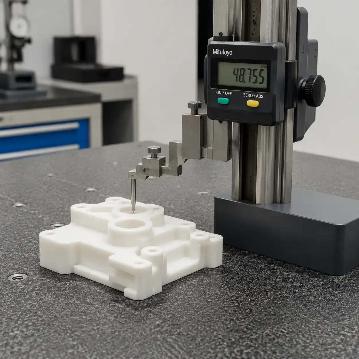
| Methode | Nauwkeurigheid | Beste voor | Kostenniveau |
|---|---|---|---|
| Caliper | ±0,02mm | Quick checks, simple features | $ |
| Micrometer | ±0.001mm | Wall thickness, precision diameters | $ |
| Gauge pins | ±0,005mm | Hole diameters, go/no-go | $$ |
| Optical comparator | ±0,005mm | Profiles, radii, 2D geometry | $$$ |
| CMM (Coordinate Measuring Machine) | ±0.001mm | Full 3D dimensional inspection | $$$$ |
| 3D scanning | ±0.02–0.05mm | Complex freeform surfaces, comparison to CAD | $$$ |
For production QC, a combination of gauge pins (fast go/no-go for critical bores) and periodic CMM inspection (full dimensional report for PPAP/ISIR) is the industry standard.
The Cost of Tighter Tolerances
Every decimal place in your tolerance specification increases cost. Here is a practical cost pyramid for injection molded nylon parts:
| Tolerance Band | Mold Cost Premium | Part Cost Premium | Rejection Rate |
|---|---|---|---|
| ±0,5mm | Uitgangssituatie | Uitgangssituatie | 0.5–1% |
| ±0.2mm | +5–10% | +3–5% | 1–3% |
| ±0.1mm | +15–25% | +10–15% | 3–5% |
| ±0,05mm | +30–50% | +20–30% | 5–10% |
| ±0,02mm | +60–100% | +40–60% | 10–20% |
The premium is not just financial: tighter tolerances also increase mold lead time (additional EDM and polishing) and require more frequent QC inspection during production.
Conclusie en aanbevelingen
Specifying tolerances for injection molded plastic parts requires balancing functional requirements with manufacturing reality. For nylon parts, the sweet spot is typically DIN 16901 Grade B (standard) — it provides adequate precision for most mechanical applications without excessive cost premiums. Glass-filled grades can reliably achieve Grade A tolerances thanks to their lower and more predictable shrinkage. Always involve your mold maker early in the tolerance specification process: their experience with your specific material and geometry is worth more than any general standard.
Veelgestelde vragen
Wat is de kleinste haalbare tolerantie voor spuitgegoten nylon?
For unfilled nylon (PA6/PA66), practical tight tolerance is ±0.05mm for dimensions under 10mm, and approximately ±0.1% of the nominal dimension for larger features. With PA66 GF30, you can reliably achieve ±0.03mm for small features due to the glass fiber’s shrinkage-constraining effect. Achieving tighter than ±0.02mm requires post-molding CNC machining.
Hoe geef ik toleranties aan op een tekening voor kunststofonderdelen?
Verwijs naar ISO 2768-mK als algemene tolerantienorm en geef vervolgens de kritische afmetingen afzonderlijk aan met strengere toleranties. Verwijs specifiek voor spuitgietonderdelen naar DIN 16901 en specificeer de tolerantieklasse (A/B/C) samen met de materiaalkrimpgroep. Geef altijd aan of de toleranties gelden bij het spuitgieten of na 24 uur conditionering, aangezien de afmetingen van nylon veranderen door vochtopname.
Verbetert of verslechtert glasvezel de maattolerantie?
Glasvezel zorgt voor een aanzienlijke verbetering van de maattolerantie door de krimp te verminderen en te stabiliseren. PA66 GF30 krimpt 0,3–0,7%, terwijl ongevulde PA66 1,0–2,0% krimpt. Glasvezel veroorzaakt echter anisotrope krimp (verschillend in de stroomrichting en de dwarsrichting), waarmee de matrijsontwerper rekening moet houden door de plaatsing van de ingang en de afmetingen van de holtes aan te passen. Het netto-effect is zeer positief voor de maatvastheid.
What does ‘free tolerance’ mean in plastic manufacturing?
Een vrije tolerantie houdt in dat voor een afmeting geen afzonderlijke tolerantie op de tekening is aangegeven en dat daarom de algemene tolerantie geldt die is vastgelegd in de norm waarnaar wordt verwezen (meestal ISO 2768-m voor kunststofonderdelen). Voor een afmeting van 50 mm volgens ISO 2768-m zou de vrije tolerantie ±0,3 mm bedragen. Vrije toleranties zorgen voor een overzichtelijkere tekening en lagere productiekosten, maar mogen alleen worden gebruikt voor niet-functionele, niet-passende afmetingen.

